A mechanical lock is a security device that uses physical components, such as tumblers, pins, levers, and bolts, to prevent access or movement unless a specific key or combination is used.
Unlike electronic or digital locks, mechanical locks operate entirely without electricity or batteries, relying solely on the precise interaction of their internal parts.
Read on how do mechanical locks work and learn about popular mechanisms like pin tumbler locks, wafer tumbler locks, and wheel combination locks.

Understanding Mechanical Locks: Types, Mechanisms, and Security Levels
Mechanical locks are ingenious devices that rely on physical components to provide security. Here’s a breakdown of how they work, based on the examples provided:
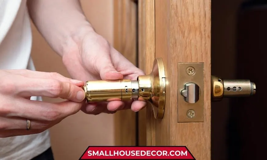
1. Doorknob Locks
- Mechanism: These locks typically use a simple rotating cylinder with a cam or lever attached. When you turn the knob, the cam either retracts a spring-loaded latch or engages it with the door frame.
- Security: Basic doorknob locks offer minimal security, often vulnerable to forced entry or picking.
2. Deadbolt Locks
- Mechanism: Deadbolts feature a solid bolt that extends into the doorjamb. They use a cylinder with pins or tumblers that align with the correct key, allowing the cylinder to turn and retract or extend the bolt.
- Security: Deadbolts offer much greater security than doorknob locks due to their solid construction and resistance to physical attacks.
3. Padlocks
- Mechanism: Padlocks consist of a shackle (the U-shaped part) that secures an object and a body containing the locking mechanism. This mechanism can be a series of tumblers that align with a key, or a combination of rotating discs or wheels.
- Security: Padlock security varies widely depending on the quality of materials and the complexity of the locking mechanism.
4. Cam Locks
- Mechanism: Cam locks use a rotating cam that is attached to a cylinder. When the key is turned, the cam rotates and either blocks or allows movement of a bolt or other locking component.
- Security: Cam locks are generally used for low-security applications like cabinets and drawers.
5. Combination Locks
- Mechanism: These locks use a series of numbered wheels or discs. Each wheel has a notch, and when the correct combination is entered, the notches align, allowing a bolt or other locking mechanism to move.
- Security: Combination locks offer decent security, but can be vulnerable if the combination is easily guessed or if the lock is of poor quality.
6. Bicycle Locks
- Mechanism: Bicycle locks employ various mechanisms. U-locks use a hardened shackle that locks into a body containing a tumbler mechanism. Cable locks use a flexible steel cable wound around a core, secured by a lock mechanism similar to a padlock.
- Security: Security levels vary greatly. U-locks generally offer higher security than cable locks, which can be cut with bolt cutters.
7. File Cabinet Locks
- Mechanism: These often use wafer tumblers, a simpler version of pin tumblers, or disc tumblers. When the correct key is inserted, the tumblers align, allowing the lock cylinder to turn and release the drawer.
- Security: File cabinet locks provide basic security to deter casual access to documents.
8. Window Locks
- Mechanism: Simple window locks use a bolt that slides into a slot on the window frame. More complex ones use keyed cylinders or levers that engage with the frame.
- Security: Window locks add a layer of security against forced entry through windows.
9. Gate Locks
- Mechanism: Gate locks can use various mechanisms, including keyed cylinders, combination locks, or simple latches. They are designed to withstand outdoor conditions and provide secure closure for gates.
- Security: Security depends on the type of lock and its construction.
10. Steering Wheel Locks
- Mechanism: These devices typically consist of a bar that attaches to the steering wheel, preventing it from turning. The bar is secured by a lock mechanism, often a pin tumbler or combination lock.
- Security: Steering wheel locks act as a visible deterrent to car theft and provide an additional layer of security.
Mechanical locks are reliable and widely used due to their simplicity and effectiveness. However, their security can vary greatly depending on the design, materials, and quality of construction.
Also Read: Curious about advanced locking technology? Discover how hydraulic locks function and their applications in various industries.
Pin Tumbler Lock Mechanism

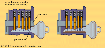
This image illustrates the functioning of a pin tumbler lock mechanism, commonly found in door locks. Here’s a breakdown of how it works:
Left Side (Lock Engaged):
- When no key or an incorrect key is inserted, the pin tumblers are misaligned.
- The pins are divided into driver pins (upper) and key pins (lower).
- The pins are pushed down by springs, and the misalignment causes the pins to block the cylinder’s rotation.
Right Side (Lock Disengaged):
- When the correct key is inserted, the ridges on the key align the key pins and driver pins at the shear line (the boundary between the cylinder and housing).
- Once the pins are aligned at the shear line, the cylinder can rotate freely, allowing the bolt to be moved and the lock to open.
The Components:

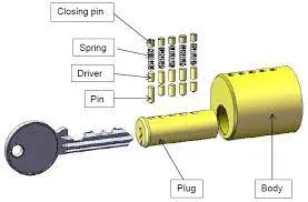
This image provides a detailed diagram of a pin tumbler lock mechanism with labeled components. Here’s an explanation of each part and how the lock functions:
- Key: A uniquely shaped metal object designed to match the lock’s pin configuration. Its ridges push the pins to specific heights when inserted.
- Spring: These apply downward pressure on the pins, ensuring that the pins return to their default position when the key is removed.
- Driver Pins: Upper pins that block the cylinder (plug) from turning if they are not correctly aligned at the shear line.
- Key Pins: Lower pins that rest directly on the key when it is inserted. Their lengths vary to match the key’s ridges.
- Plug: The rotating cylinder where the key is inserted. It can only turn if the pins align at the shear line.
- Body: The outer housing of the lock, containing the plug and pin chambers.
- Closing Pin: Ensures the system is sealed and secure.
This design is highly secure because only the correct key can align all the pins properly at the shear line. If you have any further questions or need additional explanations, feel free to ask!
Also Read: If your mechanical lock fails and you’re stuck outside, read locked out solutions to learn what steps you can take.
Among the most popular lock mechanisms are the Pin Tumbler Lock, renowned for its precision and reliability; the Wafer Tumbler Lock, valued for its simplicity and versatility; and the Wheel Combination Lock, offering keyless convenience with a focus on memorized security.
Let’s explore how these locks work and what makes them unique in the realm of mechanical security.
Wafer Tumbler Locks Mechanism

This image depicts the functioning of a pin tumbler lock mechanism in three stages, with a focus on its operation. Here’s the breakdown:
1. Left Panel – Locked State (No Key or Wrong Key):
- Pins Misaligned: The driver pins (red) extend into the gap between the plug (cylinder) and the outer housing (body).
- Shear Line Blocked: Because the pins are not aligned at the shear line, the plug cannot rotate.
- Result: The lock remains in a locked state, as shown by the red arrows indicating resistance.
2. Middle Panel – Correct Key Inserted:
- Key Inserted: The correct key’s ridges push the key pins (yellow) and driver pins (red) to their proper heights.
- Alignment Achieved: The pins align perfectly at the shear line (boundary between the plug and housing).
- No Obstruction: The shear line is clear, enabling the plug to rotate.
- Preparation for Unlocking: The lock is ready to disengage.
3. Right Panel – Unlocked State:
- Plug Rotates: With all pins aligned at the shear line, the plug rotates freely within the housing.
- Lock Opens: This rotation allows the mechanism to disengage the locking bolt, unlocking the lock.
- Key Functionality: The key’s unique pattern is essential for aligning the pins to enable this rotation.
Key Concept:
The key’s ridges correspond precisely to the varying heights of the key pins. If the wrong key is used, the pins will not align at the shear line, and the plug will remain stationary, keeping the lock secure.
This design is widely used in everyday locks due to its simplicity and effectiveness. Let me know if you have further questions!
Wheel Combination Locks Mechanism
Curious about how a mechanical lock works? Well then this video is for you!
Let’s break down the mechanism of a wheel combination lock, focusing on how dialing the combination retracts the bolt and allows the safe to open.
The Core Components:
- Wheels (or Discs): These are circular discs stacked on a common spindle. Each wheel has a notch or gate.
- Spindle: The central rod that the wheels rotate around.
- Lever (or Fence): A small bar or arm that rests against the edges of the wheels.
- Bolt: The locking mechanism that prevents the safe door from opening.
How it Works (Dialing Open the Combination):
The objective is to align the notches on all the wheels so that the lever can fall into them, allowing the bolt to retract. This is achieved through a specific dialing sequence. Let’s assume a three-wheel lock for simplicity:
- First Number (Left Turns): You turn the dial to the left several times (usually at least four) past the first number of your combination. This action engages all the wheels and sets them in motion. Then you stop precisely on the first number. This positions the notch of the first wheel under the lever.
- Second Number (Right Turns): You then turn the dial to the right past the first number, going past zero, and stopping precisely on the second number. This action disengages the first wheel and engages the second wheel. This positions the notch of the second wheel under the lever.
- Third Number (Left Turns): You turn the dial to the left, going past the second number, and stopping precisely on the third number. This disengages the second wheel and engages the third wheel. This positions the notch of the third wheel under the lever.
The Critical Last Step (Bolt Retraction):
After setting the third number, a crucial final step occurs: a final turn to the right. This final right turn performs two key actions:
- Aligning All Notches: This ensures that all the wheel notches are perfectly aligned with the lever.
- Retracting the Bolt: This is the key part. As you make this final right turn, a mechanism within the lock engages. This mechanism is directly linked to the lever. As the lever falls into the aligned notches of all the wheels, it simultaneously pulls or pushes a connected component that retracts the bolt into the lock case.
Why the Bolt Retracts on the Last Right Turn:
The design of the lock is such that the lever’s movement, when it drops into the aligned notches, is mechanically linked to the bolt’s movement.
This link could be a simple lever system, a cam, or a more complex mechanism. The important point is that the final right turn completes the process of both aligning the wheels and triggering the bolt retraction.
Opening the Safe:
With the bolt retracted into the lock case, it is now out of the path of the bolt work (the mechanism that secures the safe door). You can now turn the safe’s handle and open the door.
In summary, the wheel combination lock works through a precise sequence of turns that align notches on multiple wheels. The crucial final right turn not only completes the alignment but also triggers the retraction of the bolt, allowing the safe to be opened.
Also Read: For fast and reliable solutions to mechanical lock issues, consider contacting emergency locksmith services for professional help.
Door Knobs Mechanism

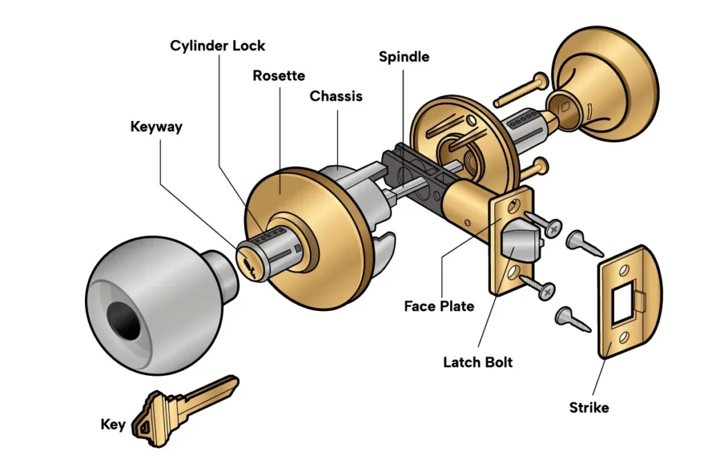
This image shows an exploded view of a cylindrical door knob lock, illustrating its key components and how they fit together to secure a door. Here’s an explanation of each labeled part:
- Key: Used to operate the lock by inserting it into the keyway to engage or disengage the locking mechanism.
- Keyway: The slot where the key is inserted to turn the cylinder lock and retract or extend the latch bolt.
- Cylinder Lock: Contains the locking mechanism that engages with the key to control access to the door.
- Rosette: A decorative cover plate that surrounds the chassis and provides a finished look to the door knob.
- Chassis: The internal housing that holds the working components of the lock and connects to the spindle.
- Spindle: A metal rod that connects the two knobs on either side of the door and rotates when the knob is turned to retract the latch bolt.
- Face Plate: A metal plate that covers the latch bolt assembly and provides a finished look when the lock is installed on the door.
- Latch Bolt: The spring-loaded bolt that extends into the door frame to keep the door closed and retracts when the knob is turned.
- Strike: A metal plate installed on the door frame where the latch bolt fits to secure the door when closed.
- Screws: Used to attach various components to the door, such as the face plate and strike.
How It Works:
- When the key is inserted and turned in the keyway, it rotates the cylinder lock, allowing the spindle to turn.
- Turning the spindle retracts the latch bolt, allowing the door to open.
- When released, the latch bolt extends back into the strike to secure the door.
This type of lock is commonly used for interior doors in residential and commercial buildings due to its ease of installation and reliable function.